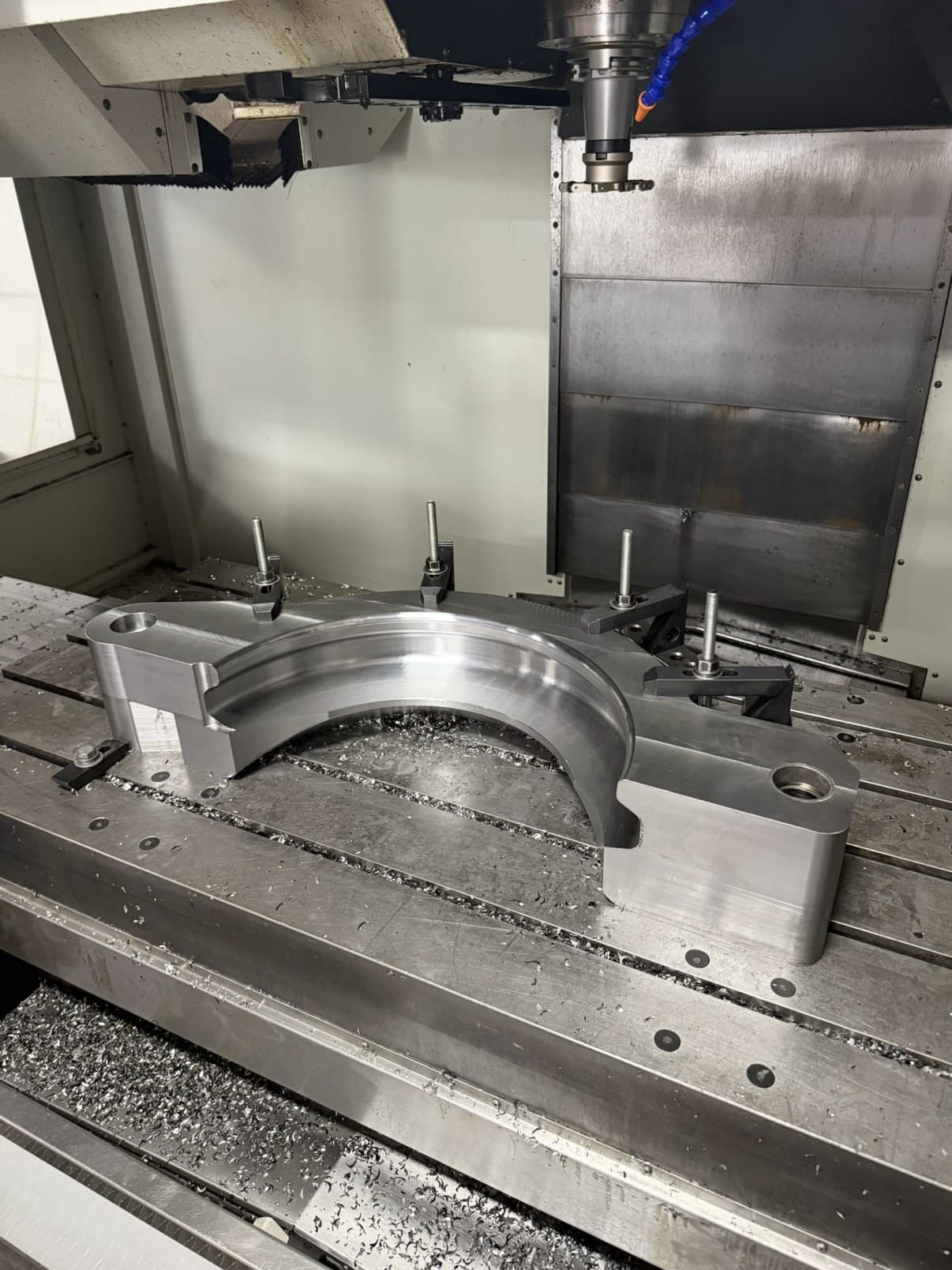
CNC milling
Pockets, profiles, holes, slots, and machined faces. Vertical milling for plates, brackets, housings, fixtures, and other components.
MILLING / TURNING / CAD-CAM
One repair part or repeat production. A small component or a large workpiece. We’ll review any machining job that fits our CNC equipment and capabilities.
Discuss your part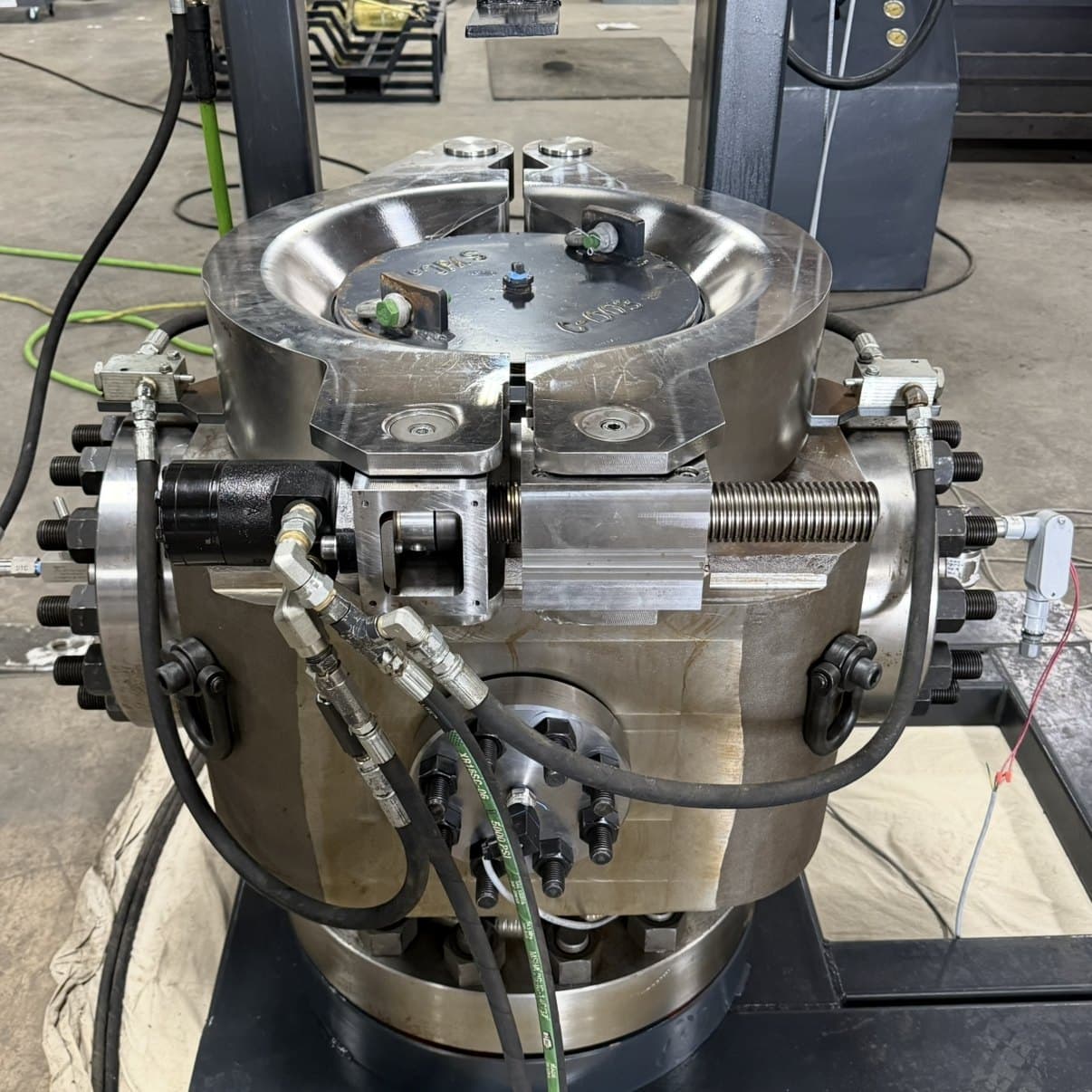
ACTUAL WORK / CNC MACHINING
FabCon machined the bowl, hydraulic motor housing, and the finished jaws fitted around the top of this assembly.
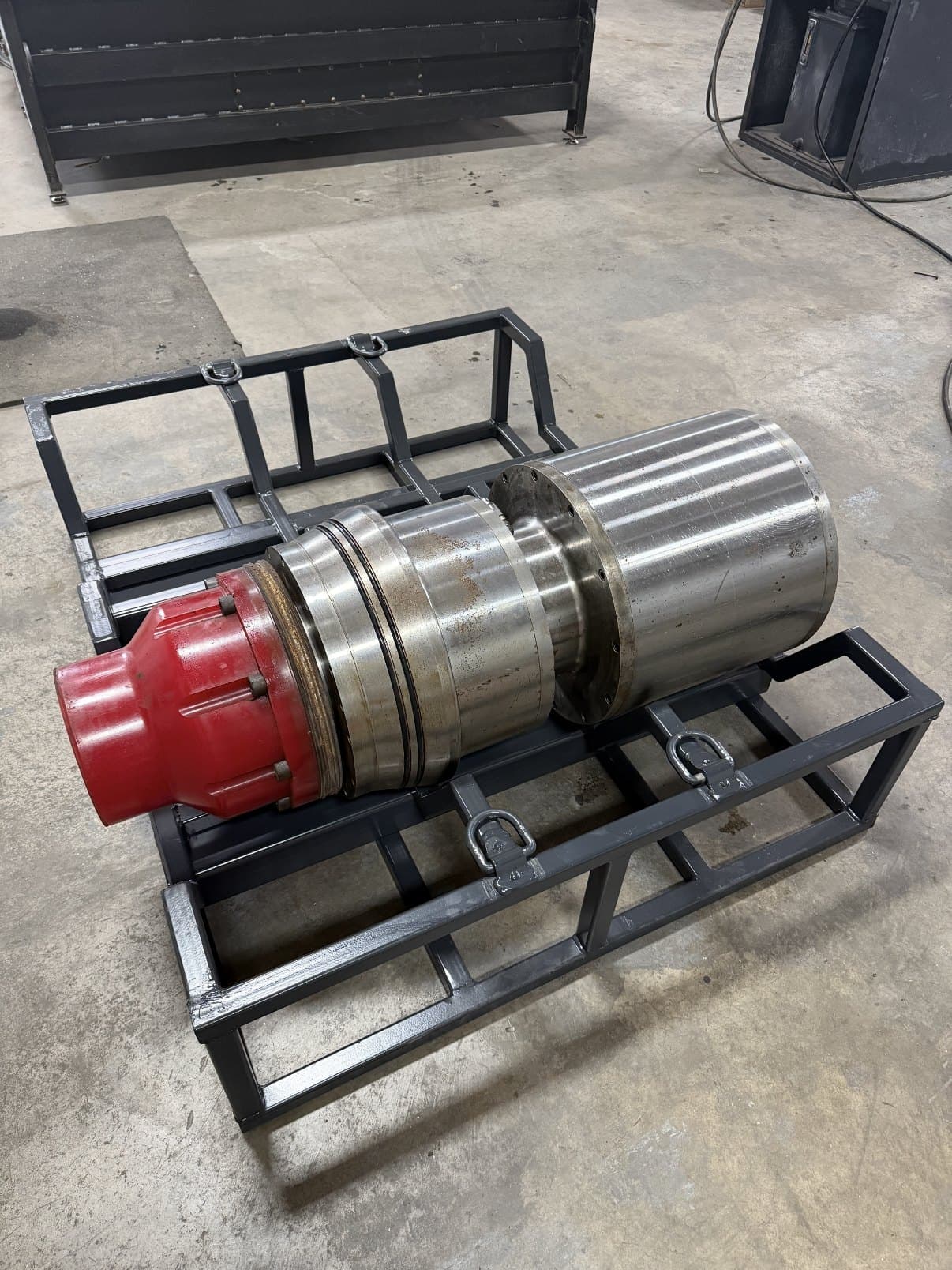
ACTUAL WORK / CNC MACHINING
FabCon machined the entire bearing assembly, shown here on its transport skid.
WHAT YOUR PART CALLS FOR
Work from a print, model, sketch, or sample. We’ll discuss the material, features, and setup needed to make your part.
Pockets, profiles, holes, slots, and machined faces. Vertical milling for plates, brackets, housings, fixtures, and other components.
Large and multi-sided parts on the HAAS EC-1600 horizontal machining center, with its integrated fourth axis.
Turning, facing, and boring for round industrial parts on the Hyundai Wia LV 800R vertical lathe.
Design and programming support to work from your drawing or model—or discuss replacing a worn, broken, or obsolete component.
THE MACHINES BEHIND YOUR PART
Dimensions are a starting point. Send the drawing so we can confirm the tooling, workholding, and setup.
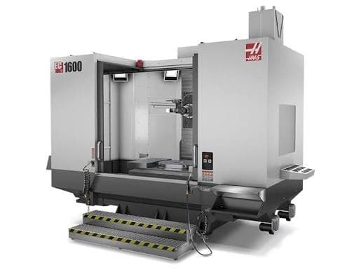
HORIZONTAL MILLING
64 × 50 × 32 in
X / Y / Z travel
Large-frame horizontal machining center for heavy parts, precision milling, drilling, boring, and multi-side machining.
Final capacity depends on part shape, fixture, tooling, and setup.
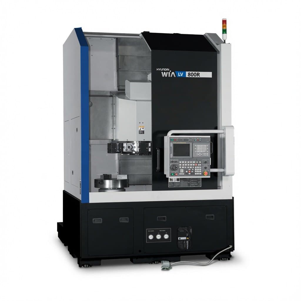
VERTICAL TURNING
Approx. 31.5 in
Maximum turning diameter
Built for large round parts, heavy turning, face work, boring, and industrial components.
Final capacity depends on part shape, fixture, tooling, and setup.
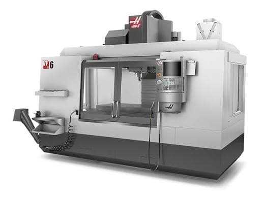
VERTICAL MILLING
64 × 32 × 30 in
X / Y / Z travel
Large vertical machining center for plates, brackets, housings, fixtures, and general CNC milling work.
Specifications are based on the standard Haas VF-6/40 configuration. Usable capacity may vary depending on tooling, fixturing, machine options, and setup.
ONE PART. THREE STAGES.
Follow the jaw segments from CAD/CAM to machining, then see the finished jaws fitted to the RCD bowl.
Model the jaw and program the machining toolpaths.
Machine the steel jaw segments in-house across multiple setups.
View the finished jaws fitted to the bowl assembly.
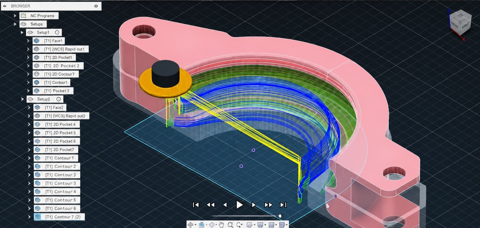
The starting point: toolpaths programmed and simulated in CAD/CAM.
Yes. Send photos and describe what is worn, broken, or needs to change. We can discuss working from the existing part, a sketch, a drawing, or a 3D model.
We consider one-off parts, prototypes, repair work, and repeat production. The starting point is whether the part, material, and requirements fit our equipment and setups.
Our listed materials include carbon steel, stainless steel, aluminum, and tool steel. Tell us the grade and whether you are supplying the material so we can confirm suitability.
Include the required tolerances and critical features with your drawing. We will review them for the specific part and setup before agreeing to the work.
Send the drawing or model if available, material, quantity, critical dimensions or tolerances, and needed-by date. Photos help when replacing a worn or broken part.
LET’S TALK ABOUT YOUR JOB
A drawing. A model. A part that needs replacing.
We’ll work through the requirements with you.